towell@sztuowei.com


Get in touch.
Dear,I will reply in 12 hours. All your message are protected!
Rapid Prototyping Services, Professional manufacturer of CNC Prototyping and 3D Prototyping in China.
3D printer is a great invention.
I allow users to print (almost)
Anything he/she can imagine!
But it's quite expensive there.
Of course, you can buy a cheap prefabrication for $200, but the printing area is small and the quality is not the best.
At the end of the order, their other famous printer, but its price is $2199.
So what to do, spend a lot of money on good prints, or spend less money on lower quality prints?
Or do it yourself! !
When I searched for printer a, I stumbled upon the term RepRap.
RepRap stands for: 'Copy quick prototype', in other words, you can print your own printer.
The most stable forward design is 'Mendel', which consists of a basic fit angle frame with four stepping motors for X, Y and Z motion.
Here is a description of how the 3D printer works.
The 3D printer deposits a small amount of molten plastic drops/wires from the head (nozzle).
It melts ABS in most cases (
Ding benzene)or PLA(
Lactic acid made from corn starch or sugar cane).
After contact with the surrounding air, the in cools into a solid state.
The printer moves the nozzle in three ways and deposits the plastic in a 3D model.
It starts at the bottom and puts the plastic down layer by layer to form a complete shape.
How small is its deposit line and how smooth it will be to print.
EBay if the full set to create a 'reprap mendel' for you '.
It's easy but a bit expensive and not fun :)
If you want to buy a kit, there is a complete set of manuals online.
It is also possible to assemble the printer through pre-made.
good start is $1200 but I want to build my own as I can. Where to begin?
The framework is a good start, it is the center of the whole project.
After looking at some of the designs of the standard 'mandel', I can draw a picture: the rest are most of the default files used on the RepRap website.
I changed some of them because it will be made of wood instead of printing. I added a .
ZIP file with all parts.
Everything in PDF and AutoCad files (DWG).
Size in mm!
After I designed all pats, I thought it would be nice to see the 3D design before starting the build.
In this way I can understand the scale of the project and show any design flaws.
I build all projects separately using Inventor.
After making all the parts, I put them in one assembly.
After I put everything together, something needs to be changed in the drawing (
The file in the previous step is the last oneI added a .
ZIP file with all parts.
All the files are prepared for ventorfirst. The frame is the center of the build and all the parts are attached to the frame.
makes all parts like this :-
Print the drawings of the parts that need to be made. -
Take a pencil, a calligraphy, tape.
Measure and draw things directly. -
Draw a top view on the wood. -
Saw the part with the correct shape. -
Drill holes where needed. -
Measuring parts :-
If it is correct, you can enter the next part. -
If it is small, start again and look out, 'measure cut once twice '--
It's too big, try to make it the right size.
After the main frame, I created z-
After 2 failures trying to create the X carrier, I decided to print the original part through the 3d hub.
I found someone printed my part with ABS.
The part I designed was made of wood.
Or I don't have the right tools to make them.
Of course, I can't build the entire printer myself.
So I purchased these parts from eBay, the Web store or the local hardware store. List of parts:-
Arduino's MIGA 2560. -Ramps 1. 4. -
5x 4988 step drive. -Heated bed. -HotEnd (Budaschnozzle). -
Intelligent LCD controller. -
Mechanical end-Cooler fans-
100 NTC thermal resistors of 100 k ohmsLots of wires. -T5-
12 teeth pulling and timing beld-
2x5mm to 8mm axis coupler. -
12x LM8UU linear bearing. -
10x dial 608zz bearing. -
Greg's hinge extruder kit. -
5x Nema17 step machine (1. 7, 40mm, 48Oz. in)-
Steel m8 thread 4 m. -6 pre-
Cut Bar. -
Ikea mirror 20mm x 20mm. -
There are many m3 nuts and bolts. -Zip Ties.
More random small parts can be thought of at this moment.
Most of the hands start putting the frame together.
I calculated that the space between frames must be 31 cm.
The frame is connected by 7x M8 steel thread.
2 of the bottom threads used to install Y-axis stepper.
2 more places to fix the Y-bearingaxis belt.
The heating bed is next.
I drilled a 15mm hole in a piece of wood and cut it in half.
This is perfect for mounting bearings.
These pieces stick to the board, and on this board, I installed another board with a spring between them for leveling the head bed.
At the bottom of the heated bed, I placed a thermal resistor to control the temperature.
At the top of the bed I placed an Ikea mirror of 20mm x 20mm for creating a smooth plane to print.
To make this work (
Maintain good quality of pints)
I ordered 3 printed parts.
2 for connecting X-axis to the Z-
Shaft and 1, for installation of hot end.
To move the extruder carrier, I used a timing belt, mounted on two outermost blocks, one and one simple bearing, and the other end is a stepping motor with a pulley. The Z-
The shaft is moved by 2 stepping motors.
These are connected to two M8 threads via a coupler.
The printer used 12 v for extra traction, a lot.
I used an old ATX power supply and cut off all 5 v and 3 v power supplies. 3v leads.
Bundle the two tracks together (12v and 12v1).
Used to power a 5 connection and another to power a 11a connection.
Control the power supply connected to the green line (power on)and the black (ground)to a switch.
Now I can turn on and off 'remotely.
Next is the task of connecting all the wires to the correct pins.
I used the image on the RepRap website to connect all the wires.
Fortunately, it is very direct.
Since the polarity of the motor and the thermal resistor is not a problem, the connection is clearly marked. the 3 end-
It's easy to connect to stop, ,-To -
And send a signal to the signal.
If the motor turns in another way, don't worry, this can be corrected in the Arduino firmware.
As mentioned, I print and create Gcode using Cura: Download: install Cura and start it. -
The first is to set up the printer: Browse the settings. -
After the settings are complete, you can change most of the settings. -
good idea is to change the print speed to a low value (50)
, This can be changed back after the printer is pre-formed. -
Measure your filament at 3, add the numbers, divide by 3.
Set this value to 'diameter (mm)” -
Set the print temperature according to the temperature you need to use the filament.
Go to the advance tab :-
Set the nozzle diameter.
Open the expert settings using 'Ctrl' 'E.
If your cooling fan (if mounted)
Blowing directly to hotend, it is wise to turn down the fan speed maxThe rest of the settings can be changed according to your preference.
But keep in mind that it will mess up your print. For testing (moving axis’s)
I use PrintRun just because it is easy: P download: There are two main firmware for the ramp. -Merlin-
SprinterI uses the Merlin software because the printed photos are better than Sprinter.
Download from: currently I am using Cura 14.
01 for creating gCode.
Arduino uses gcode to position the print head and squeeze out, and there's certainly more.
It is even possible to print directly from the PC via a USB cable connected to the Arduino.
To change the settings when uploading software to Arduino, you need some software.
You need Arduino 0.
The best result is 23.
See the file 'arduino-0023.
After installing the software, extract the Merlin firmware and turn on 'Marin '. PDE” file.
Go to configuration '. h” page.
All settings are here.
Will go through all this step by step.
I will only display the basic settings.
There are more in this configuration.
The line number and value are from the default profile.
In the added zip file, you will find that the default and custom file line nr: 73 # define motherboard 7 has the electronic motherboard type set. default is 7 (Ultiemaker)
But I used ramp 1 for this project.
I used nr 33 row nr: 77/# define _ mendelname 'Beast of Bram' just for fun and I named my printer which is shown on the LCD at the beginningup.
Line 84th: # define extruder 1 this setting the number of extruder owned by the printer.
The default is 1 line nr: 124/127 temp _ sensor extruder with a thermal resistor attached to the head bed.
This is used to measure the temperature.
It is important to get the correct value, otherwise the extruder of the bed will overheat or get cold.
If you know which thermal resistor is used, all you need to do is fill in the correct number. -
# Define temperature _ sensor _ 0 is the main extruder thermal resistor-
# Define temperature _ sensor _ bed is heating bed temperature if only 2 Thermal resistors are used, you can fill in 0 in the other 2 lines above the nr 124 line, list the list containing common thermal resistors
If you are not sure of the type of thermal resistor being used, please download the data spoofing of the thermal resistor.
Connect the thermal resistor to the multimeter and measure its resistance to check the temperature.
And cross-reference it with the table in the data table.
Row nr: 234 # define _ danger _ extrudethis is used to prevent the extruder from moving when the hot end is cold.
I commented it out for testing purposes.
Line nr: 301/306 # define inver _ dir true these lines are used to define the direction of the motor's rotation.
After the connection, all end stops and step-ins start the printer, connect it to the PC and use 'Printrun '.
Printrun enables you to not only print the axis, but also move it.
I moved the axsis 10mm to confirm that the Walker is on the right path.
If not: change True to False on the axis, save the file and upload it again. (
If the stepping motor is not running properly, please go to the next step first)
Line nr: 313/319 # defines x_max_pos 205 this sets the maximum and minimum limits for the printer.
The minimum value of 0 should not be changed (
Except that you want your home in the center of the bed)
The Max is easy to find.
Using a printer, move the head using a printer or LCD screen.
Move the shaft before the head leaves the bed.
Check the distance of the move and change this distance in the firmware. (
If the stepping motor is not running properly, please go to the next step first)
Line nr: 403 # defines default _ axis_steps _ per _ unit which is the most difficult part of the setup.
The following is to determine how much the motor must turn in 1 step.
1 step = 1 MMI uses this site: Get the values for the x and z axes.
Go to Site a and fill in varaibles.
Default steps :{78. 7402 , 78. 7402 , 200. 0*8/3 , 760*1. 1}78.
7402 = axis_steps _ per_unitx, 78.
7402 = AXIS_STEPS_PER_UNIT_Y, 200.
0*8/3 = ste _ steps _ per _ unit _ z, 760*1.
1 = the value I use :{53. 33 , 53. 33 , 2560. 00 , 515. 91}To test this,-Save the code. -
Upload to Arduino. -Start Printrun. -Home the axsis. -
Measure the distance from a fixed point to the point to be moved, such as the x-axis carrier. -
Write down the measured values. -
Move an axis 50mm-
Measure the distance again and write it down. -
Calculate the distance the printer moves. -
If it equals 50mm of what you are moving in the software: Congrats, this axis is set correctly!
Go to the next axis. -
If not: use the next formula to calculate the next value to try :(
Set value/actual move value * 100)= new value; for example: (53. 33 / 55 * 100)= 96.
Set the value 96, try again!
I use the website to calculate these values and it will work right away.
The extruder is another story.
For this job :-
Put a piece of filament into the extruder and clamp it.
Don't put the threads too low.
About 2 cm.
It has to move 2 cm down-
Stick a piece of tape on the filament. -
Measure the distance from the tape to the extruder. -
Move the extruder 1 or 2 cm down. (with printrun). -
Measure the distance again and calculate the travel distance. -
It would be great if it was equal to the given distance.
If not, please try again using the formula above! (
If LCD is connected)Row nr: 470.
Uncomment the code of the LCD screen you are using.
The rest of the code is fine and you can read it through to fine tune or set some other values.
But these are the values that need to be set.
Co-driver, walkers may move out of the box directly.
Whether or not: PEither way, it is a good idea to adjust the drivers, which will strengthen the motors, make them run smoothly and stop them and the drivers from overheating.
There are two ways to do this: do this (1): To do this (2)
: Source: 4988 data sheet [[1]]
The calculation of the maximum trip current is: triptripmax = Vref /(8*Rs)
The sensing resistance is Rs = 0 using Pololus.
05 Ohm, so Vref is 0.
4 the maximum current of 0 should be generated. 4/(8*0. 05)=1.
Another example is that by using max 0, the temperature rise at 50% of the rated step motor for 1 is targeted.
So rearrange it as: Vref = I _TripMax * 8 * Rs orVref = 0. 7 * 8 * 0. 05 = 0.
280 v, the measured Vref is 0.
273 V, I should expect 0.
6825, I measure a current of 0 through a coil.
486 full-step mode should be 0.
7071 of the full stroke current, or I _TripMax = 0. 486/0. 7071= 0.
It seems that 68 7 is close enough.
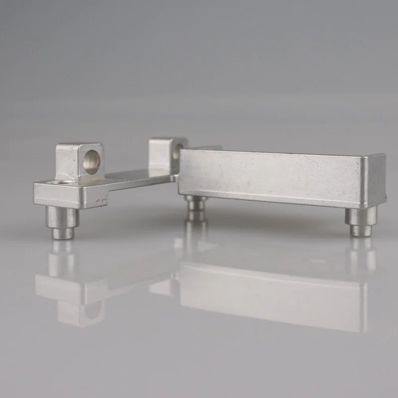
The Vref signal can be accessed as a 'VREF' pin on the carrier with a voltage regulator because of
There is no punching on the bracket, and there is no punching on the two brackets as the wiper for the decorative tank itself.
The next step is to test the printer and its settings.
It's convenient to read the next post before you print: heat the parts.
Everything was there for the first time.
Therefore, power on the printer and set the bed temperature to 50 or 60.
Stay heated in bed.
Stay with your printer.
If there is a problem, it is important to turn off the power of the printer.
Try to measure the temperature of the bed, I use the infrared temperature 'gun '.
If everything is OK, power the bed and power the Hotend.
First 100C, then 50c and 200C.
Try to continuously measure the temperature and cross check the temperature with the software to ensure that the temperature is at the same level (or very close).
This is to prevent fatigue.
Okay, now is the time to print! ! ! !
Load the filament into the extruder.
Download the test file (20x20mm box)
You print the work.
Congrats! !
If not, try to find out what's wrong with it :-
Small tension on the belt-
Driver not adjusted correctly-
The bed was not flat. Try theagain.
If you're really stuck
Send me a message :)
Cost: The money I spend on this printer is uncertain.
I think about 350 euros. 470 dollar).
I will add up all the expenses soon.
Yes, it's more expensive than a cheap premade 3D printer.
But it's much more interesting and educational than pre-made printers.
Now that the printer is working, you can start the print upgrade for the printer.
Pattfor pats and other interesting things to print! !
For more information about my printer, please visit my website :(Dutch)
For more information on RepRap and its software and hardware: any comment questions, please do not hesitate to recommend or send me a message! !
few months later, I noticed that there were some games on the x and y axis.
© 2005-2025 Shenzhen Tuowei Model Technologies Co., Ltd. | All Rights Reserved 粤ICP备11096697号