towell@sztuowei.com


How to Price CNC Machining Services
build a laser 3d printer - stereolithography at home
by:Tuowei
2019-08-12
Here is how to make a 3D printer for stereo printing.
This is still a work in progress, but so far it works well.
This is mainly an experiment, starting with a Delta robot stereo printer and ending with a more traditional Descartes stereo printer.
This is the part list I used. General Parts 3-
16 \"x 171/2\" x 3/4 \"plywood on the back and side of Case2-
16 \"x 3/4\" plywood at the top and bottom of the bottom cover-
6x3 \"wooden screws and laundry detergent 4-
Rubber stopper 1 7/8 \"x 1 3/4\" 4-1/4-
20x2 1/2 \"Bolts8-1/4-
20 nuts and
4 \"x 1/4\" Black Acetate Tablets (Delrin)1 -
BeakerLinear railway and block from automation overstock 4-1 liter
AG linear guide rail 15mm x 200 mm²-
2 Bolt flange2-15 mm bearing block
Sparkfun and other 6 15mm bearing blocks, 4 Bolt flange electronic parts
Miniature switch with rold3-ROB-
09238 stepping motor
Step driver (EasyDriver)
Drivers should also work)3 -
Polarized connector 4-Pin housing3 -
Polarized connector 4-Pin Header2 -
6 pin female head 2-
DC barrel jack adapterFemale1 -Sanguino (
Arduino Mega can also modify the code)1 -
5 v ftdi usb Cable 1-Omron G5V-1 Relay1 -LD33V 3.
3 v voltage regulator 2-
9 V 500ma or higher power supply (
Can use one, but very cheap)1 -12V -
24 v and above power supply (
For stepping motor)1 -
Transistor 1-1K Resistor1 -
1N41482 and other protection diodes-
2-pin screw terminals for men and women.
1 \"head, wire and prototype plate large enough to hold all screws for McMasterCarr1 -
1018 carbon steel precision Acme rebar, 1/4 \"-
16 Size 3\' longitudinal nut from DumpsterCNC3-Acme 1/4\"-16 (1 Start)
Square flange 4 hole3-Acme 1/4\"-16 (1 Start)
Color 5mm BoreLaser parts Aixiz1-
Blue laser glass lens1-
20mW1-Aixiz 40 nm purple laser
Iris diaphragm, zero aperture, UV/visible light curing resin from Edmund opticthe 21mm outer diameter from Ellsworth adhesive 1-1
3099 liter Dymax super light-
Welding joint 1-
Need 3105 light curing adhesive tool for drill bit and various drill bit
40 tapAccess to CNC MillGorilla glue orsimilarLong clampacksawfilesfetylaser goggles and so on.
To be effective, they must protect the light of 40 nm.
Well ventilated area, do not breathe in the steam generated during resin or curing.
Mark, drill and tap with 6-
32 tap the bottom of the stepping bracket.
Connect the stepping bracket to the bottom plate with 6-
32 machine screws.
Connect the stepping motor to the stepping motor.
M3 screws for my step
Use 4-install the linear guide rail on the bottom plate
40 screws and nuts each.
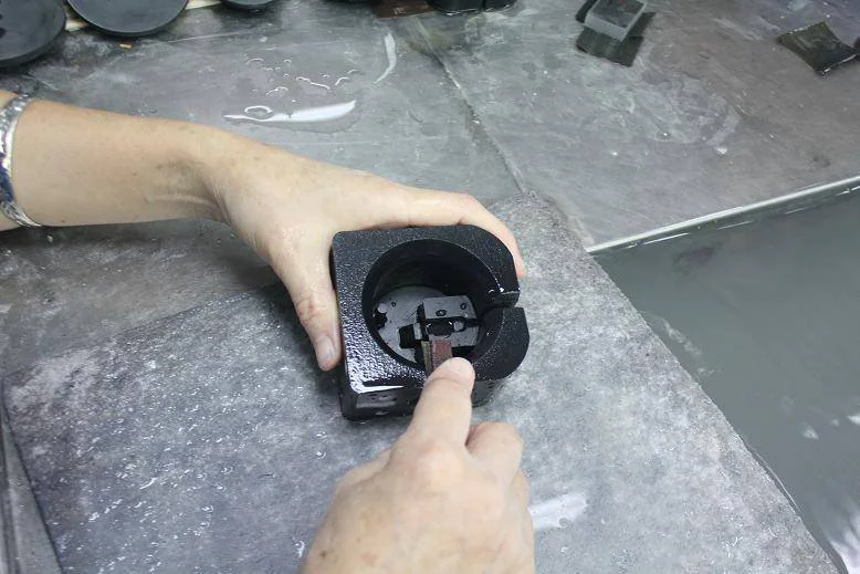
Drill holes on the laser mounting flange and mount to the 2-hole bearing block. (
I know it shows a block of 4 holes in the picture and you should use a block of 2 holes. )
First place the guide rail into two bearing blocks, make sure to push out the plastic bearing holder with the guide rail.
The plate is then screwed onto two bearing blocks.
Check to ensure that the track is parallel by measuring the spacing at both ends of the track.
Then check that they are square with the plate.
If they are not parallel then loosen the screws, adjust until they are parallel and tighten.
Once the assembly is adjusted, set it to the top of the housing and then install the stepping motor.
Screw the Acme rod into the NUT and the coupler and connect it to the stepping motor.
Once everything is lined up with Marks and drilled holes in the track to connect to the top of the shell.
Connect with machine screws, nuts and washers on the outside of the plate.
Drill the flange hole on the Z-arm bracket.
Drill and tap 4-
Install 40 holes at the end of the arm through the slot.
Please see the picture below.
The arm should be put into the slot and stick out a bit at the end.
Cut a short piece of 1/8 \"thick 2\" x 1 \"aluminum and drill holes to match the holes at the end of the ARM support.
Then put the arm into the slot, screw it on aluminum and clamp the arm in place.
Please see the picture above if you need clarification.
At the bottom of the shell, use the jigsaw puzzle to cut the holes of the z-axis stepping machine.
To install the pedometer to the bottom of the chassis, you can see the picture above, but this is actually hard to arrange properly.
You can find a piece of aluminum that is wide enough to cut a hole that matches the rounded area raised on the stepping motor.
Once the cut is done, you can mark and drill holes for the stepping machine, and then drill holes are mounted to the housing.
To install the round platform on the hand arm, just use 4-
40 tap the bottom of the arm, then drill holes on the platform and install with screws.
As shown, clip the box together to make sure everything is as square as possible.
Then follow the picture above to drill holes and screw them together with wooden screws and washers.
You can do some with flat feet bought by the store or with plugs, bolts, two washers and two nuts.
Follow the picture above.
Just drill the plug far enough to fit the head of the bolt and then drill the hole at the bottom of the shell.
Use the Bulleye bubble level to level the case by placing the case in the center of the bottom, and then turn the bottom nut of each foot to level the case. Cut three 9\" (about 228mm)
Length of ACME rod.
Archive the end so that the thread is well formed enough to put the thread into the ACME nut.
You may have to use a small triangle file to form the thread back into the available shape.
After assembling the housing, you can connect the z-axis linear guide rail to the back of the housing.
First assemble the entire z axis including linear guide rail, ACME Rod and ACME coupler.
Slide the coupler into the stepping shaft.
The guide rail should be flush with the back of the housing, if not then you may need to adjust the position of the Z step.
Place the track in the picture above and mark the 4 sides.
Take the Z component back.
Measure the track from the end of the first hole to the center, then measure the space between the other holes, and mark the line on the track profile on the back of the chassis.
Find the center of the mark on the back of the box and draw a line down.
The line goes through the drill to install the Z axis guide and then install it.
Drill a hole large enough at the top to allow the 4-pin connector on the stepping motor to pass through.
I might design a suitable circuit board for all of this, but since I was designing it was the most flexible setting for me.
Hope the drawings and pictures make sense and let me know if clarification is needed.
This is my first time using Fritzing, so it\'s not as beautiful as I might have done.
The Fritzing file is attached below.
First weld the polarized 4-pin connector to the Easydriver board at the top.
Then weld the male head pin into other holes on the bottom * Easydrivers.
* One thing I should do is put the head pins marked as MS1 and MS2 on top so it\'s easy to patch them to the ground or weld some heads on the prototype board
I ended up wanting to change the subdivision from the default settings for step 8 subdivision.
I have now added these jumpers on the drawings.
Once you have welded the male head, cut the female head to match, then place them on the male pin and place them on the prototype board with enough work space at intervals.
Weld the screw terminal to one end and then connect it to each head of the Pwr on easydriver. Mark + and -
On the screw terminals
I pass 6 steps and directional pins and ground to Sanguino with 10 needles and ribbon cables.
You can put a regular header line and pass the signal directly to Sanguino.
Don\'t forget to connect the ground from a different board.
The wire color of the coil pair in my stepping motor is yellow blue and green red.
Verify the step coil pair according to these instructions.
Use the pair you verified for the stepping motor to weld the female polarized head onto the stepping wire.
The sheet shows the title of the subdivision selection.
I used half step for the x and y axis and it works fine.
Use a half step to ground the jumper on the ms2 pin.
There\'s probably a better way to do this, but I\'m not an electrical engineer and the parts I use are on hand.
So far this setting works fine in my printing for a few hours.
The drawing below is a bit different from what I wired but should work.
You can also put all of this on a board, which is the biggest board I have on hand.
The laser drive plate takes 9 v out of the wall SFP power supply to drive the relay and LD33V 3.
A 3 v voltage regulator that supplies power to the laser.
The TIP120 transistor switch relay, which switches the ground of the laser to turn the laser on or off.
The limit switch prevents the controller from accidentally moving too far in one direction.
They can also be used to store machines and tell them where to start.
Weld the wires to the NC and public pins on each switch.
Put a little gorilla glue on the switch and put it on it so that the bearing block will hit the switch before going too far.
1/2 \"in from the end of the railway is OK.
Tape them in place to make sure they are in good contact with the wood.
The x-axis is glued to the aluminum plate and works normally.
If you have switches with mounting holes, you can drill and install them in this way.
I can\'t find the screws small enough to hold my mounting holes.
Extend the wire up and pull out the hole of the wire at the top of the shell.
I nailed them in place with wire nails.
Weld all the common side switch wires into the 6-pin female connector.
The NC side wire is then welded to another 6-pin female head.
Install the plate to the top of the case with screws or non-conductive double-sided foam straps.
* Do not plug in any power supply before connecting the stepping motor.
When the power of the step drive is turned on, connecting or disconnecting the step drive will blow up the drive board.
Connect the stepping motor to Easydrivers.
Connect the laser to 3.
3 v joint on laser board.
Ground the limit switch and then connect the signal to the digital pin on Sanguino. I used 17-22.
Connect the Step and Dir pins to Sanguino. I used 2-7.
Connect the laser pin to Sanguino. I used pin 23.
Make sure that the grounding of both the laser board and the stepping board is connected to the ground on the Sanguino.
Connect all power supplies.
9 v for laser board, 9 v for Sanguino, 12 v-
The stepping board is 24 v.
I connect all of these to a power strip to control them at the same time.
You can connect a head on the laser board and then connect it to the Vin pin on the Sanguino and power it from there if you want.
Connect the 5 v usb ftdi cable to Sanguino.
Mark with wire color.
If using Arduino Mega, just use the normal USB cable.
Download and install the Arduino IDE and install it.
If using Sanguino, see this page in the rest of the settings.
Download and install Replicatorg and install it.
Download the file printer.
Compress it into the Arduino Sketchbook folder or open the UVLPrinter.
Wherever you extract it.
It contains a modified version of the Sprinter firmware. Open the pins.
H tab and change any pins you may connect differently from my settings.
The Step and dir pins should be easy to find, and the min_pin and max_pin for each axis are the top and bottom limit switches.
Anything with. 1 is not used.
Everything else should be easy to figure out.
Define x _ step _ pin 6 define x _ dir _ pin 7 define x _ min _ pin 19 define x _ max _ pin 20 if you are using anything other than a half step
The H tab and change the following line.
Floating axis_steps_per_unit []= {251. 971678, 252. 4475, 1007. 87402,700};
This is still a work in progress, but so far it works well.
This is mainly an experiment, starting with a Delta robot stereo printer and ending with a more traditional Descartes stereo printer.
This is the part list I used. General Parts 3-
16 \"x 171/2\" x 3/4 \"plywood on the back and side of Case2-
16 \"x 3/4\" plywood at the top and bottom of the bottom cover-
6x3 \"wooden screws and laundry detergent 4-
Rubber stopper 1 7/8 \"x 1 3/4\" 4-1/4-
20x2 1/2 \"Bolts8-1/4-
20 nuts and
4 \"x 1/4\" Black Acetate Tablets (Delrin)1 -
BeakerLinear railway and block from automation overstock 4-1 liter
AG linear guide rail 15mm x 200 mm²-
2 Bolt flange2-15 mm bearing block
Sparkfun and other 6 15mm bearing blocks, 4 Bolt flange electronic parts
Miniature switch with rold3-ROB-
09238 stepping motor
Step driver (EasyDriver)
Drivers should also work)3 -
Polarized connector 4-Pin housing3 -
Polarized connector 4-Pin Header2 -
6 pin female head 2-
DC barrel jack adapterFemale1 -Sanguino (
Arduino Mega can also modify the code)1 -
5 v ftdi usb Cable 1-Omron G5V-1 Relay1 -LD33V 3.
3 v voltage regulator 2-
9 V 500ma or higher power supply (
Can use one, but very cheap)1 -12V -
24 v and above power supply (
For stepping motor)1 -
Transistor 1-1K Resistor1 -
1N41482 and other protection diodes-
2-pin screw terminals for men and women.
1 \"head, wire and prototype plate large enough to hold all screws for McMasterCarr1 -
1018 carbon steel precision Acme rebar, 1/4 \"-
16 Size 3\' longitudinal nut from DumpsterCNC3-Acme 1/4\"-16 (1 Start)
Square flange 4 hole3-Acme 1/4\"-16 (1 Start)
Color 5mm BoreLaser parts Aixiz1-
Blue laser glass lens1-
20mW1-Aixiz 40 nm purple laser
Iris diaphragm, zero aperture, UV/visible light curing resin from Edmund opticthe 21mm outer diameter from Ellsworth adhesive 1-1
3099 liter Dymax super light-
Welding joint 1-
Need 3105 light curing adhesive tool for drill bit and various drill bit
40 tapAccess to CNC MillGorilla glue orsimilarLong clampacksawfilesfetylaser goggles and so on.
To be effective, they must protect the light of 40 nm.
Well ventilated area, do not breathe in the steam generated during resin or curing.
Mark, drill and tap with 6-
32 tap the bottom of the stepping bracket.
Connect the stepping bracket to the bottom plate with 6-
32 machine screws.
Connect the stepping motor to the stepping motor.
M3 screws for my step
Use 4-install the linear guide rail on the bottom plate
40 screws and nuts each.
Drill holes on the laser mounting flange and mount to the 2-hole bearing block. (
I know it shows a block of 4 holes in the picture and you should use a block of 2 holes. )
First place the guide rail into two bearing blocks, make sure to push out the plastic bearing holder with the guide rail.
The plate is then screwed onto two bearing blocks.
Check to ensure that the track is parallel by measuring the spacing at both ends of the track.
Then check that they are square with the plate.
If they are not parallel then loosen the screws, adjust until they are parallel and tighten.
Once the assembly is adjusted, set it to the top of the housing and then install the stepping motor.
Screw the Acme rod into the NUT and the coupler and connect it to the stepping motor.
Once everything is lined up with Marks and drilled holes in the track to connect to the top of the shell.
Connect with machine screws, nuts and washers on the outside of the plate.
Drill the flange hole on the Z-arm bracket.
Drill and tap 4-
Install 40 holes at the end of the arm through the slot.
Please see the picture below.
The arm should be put into the slot and stick out a bit at the end.
Cut a short piece of 1/8 \"thick 2\" x 1 \"aluminum and drill holes to match the holes at the end of the ARM support.
Then put the arm into the slot, screw it on aluminum and clamp the arm in place.
Please see the picture above if you need clarification.
At the bottom of the shell, use the jigsaw puzzle to cut the holes of the z-axis stepping machine.
To install the pedometer to the bottom of the chassis, you can see the picture above, but this is actually hard to arrange properly.
You can find a piece of aluminum that is wide enough to cut a hole that matches the rounded area raised on the stepping motor.
Once the cut is done, you can mark and drill holes for the stepping machine, and then drill holes are mounted to the housing.
To install the round platform on the hand arm, just use 4-
40 tap the bottom of the arm, then drill holes on the platform and install with screws.
As shown, clip the box together to make sure everything is as square as possible.
Then follow the picture above to drill holes and screw them together with wooden screws and washers.
You can do some with flat feet bought by the store or with plugs, bolts, two washers and two nuts.
Follow the picture above.
Just drill the plug far enough to fit the head of the bolt and then drill the hole at the bottom of the shell.
Use the Bulleye bubble level to level the case by placing the case in the center of the bottom, and then turn the bottom nut of each foot to level the case. Cut three 9\" (about 228mm)
Length of ACME rod.
Archive the end so that the thread is well formed enough to put the thread into the ACME nut.
You may have to use a small triangle file to form the thread back into the available shape.
After assembling the housing, you can connect the z-axis linear guide rail to the back of the housing.
First assemble the entire z axis including linear guide rail, ACME Rod and ACME coupler.
Slide the coupler into the stepping shaft.
The guide rail should be flush with the back of the housing, if not then you may need to adjust the position of the Z step.
Place the track in the picture above and mark the 4 sides.
Take the Z component back.
Measure the track from the end of the first hole to the center, then measure the space between the other holes, and mark the line on the track profile on the back of the chassis.
Find the center of the mark on the back of the box and draw a line down.
The line goes through the drill to install the Z axis guide and then install it.
Drill a hole large enough at the top to allow the 4-pin connector on the stepping motor to pass through.
I might design a suitable circuit board for all of this, but since I was designing it was the most flexible setting for me.
Hope the drawings and pictures make sense and let me know if clarification is needed.
This is my first time using Fritzing, so it\'s not as beautiful as I might have done.
The Fritzing file is attached below.
First weld the polarized 4-pin connector to the Easydriver board at the top.
Then weld the male head pin into other holes on the bottom * Easydrivers.
* One thing I should do is put the head pins marked as MS1 and MS2 on top so it\'s easy to patch them to the ground or weld some heads on the prototype board
I ended up wanting to change the subdivision from the default settings for step 8 subdivision.
I have now added these jumpers on the drawings.
Once you have welded the male head, cut the female head to match, then place them on the male pin and place them on the prototype board with enough work space at intervals.
Weld the screw terminal to one end and then connect it to each head of the Pwr on easydriver. Mark + and -
On the screw terminals
I pass 6 steps and directional pins and ground to Sanguino with 10 needles and ribbon cables.
You can put a regular header line and pass the signal directly to Sanguino.
Don\'t forget to connect the ground from a different board.
The wire color of the coil pair in my stepping motor is yellow blue and green red.
Verify the step coil pair according to these instructions.
Use the pair you verified for the stepping motor to weld the female polarized head onto the stepping wire.
The sheet shows the title of the subdivision selection.
I used half step for the x and y axis and it works fine.
Use a half step to ground the jumper on the ms2 pin.
There\'s probably a better way to do this, but I\'m not an electrical engineer and the parts I use are on hand.
So far this setting works fine in my printing for a few hours.
The drawing below is a bit different from what I wired but should work.
You can also put all of this on a board, which is the biggest board I have on hand.
The laser drive plate takes 9 v out of the wall SFP power supply to drive the relay and LD33V 3.
A 3 v voltage regulator that supplies power to the laser.
The TIP120 transistor switch relay, which switches the ground of the laser to turn the laser on or off.
The limit switch prevents the controller from accidentally moving too far in one direction.
They can also be used to store machines and tell them where to start.
Weld the wires to the NC and public pins on each switch.
Put a little gorilla glue on the switch and put it on it so that the bearing block will hit the switch before going too far.
1/2 \"in from the end of the railway is OK.
Tape them in place to make sure they are in good contact with the wood.
The x-axis is glued to the aluminum plate and works normally.
If you have switches with mounting holes, you can drill and install them in this way.
I can\'t find the screws small enough to hold my mounting holes.
Extend the wire up and pull out the hole of the wire at the top of the shell.
I nailed them in place with wire nails.
Weld all the common side switch wires into the 6-pin female connector.
The NC side wire is then welded to another 6-pin female head.
Install the plate to the top of the case with screws or non-conductive double-sided foam straps.
* Do not plug in any power supply before connecting the stepping motor.
When the power of the step drive is turned on, connecting or disconnecting the step drive will blow up the drive board.
Connect the stepping motor to Easydrivers.
Connect the laser to 3.
3 v joint on laser board.
Ground the limit switch and then connect the signal to the digital pin on Sanguino. I used 17-22.
Connect the Step and Dir pins to Sanguino. I used 2-7.
Connect the laser pin to Sanguino. I used pin 23.
Make sure that the grounding of both the laser board and the stepping board is connected to the ground on the Sanguino.
Connect all power supplies.
9 v for laser board, 9 v for Sanguino, 12 v-
The stepping board is 24 v.
I connect all of these to a power strip to control them at the same time.
You can connect a head on the laser board and then connect it to the Vin pin on the Sanguino and power it from there if you want.
Connect the 5 v usb ftdi cable to Sanguino.
Mark with wire color.
If using Arduino Mega, just use the normal USB cable.
Download and install the Arduino IDE and install it.
If using Sanguino, see this page in the rest of the settings.
Download and install Replicatorg and install it.
Download the file printer.
Compress it into the Arduino Sketchbook folder or open the UVLPrinter.
Wherever you extract it.
It contains a modified version of the Sprinter firmware. Open the pins.
H tab and change any pins you may connect differently from my settings.
The Step and dir pins should be easy to find, and the min_pin and max_pin for each axis are the top and bottom limit switches.
Anything with. 1 is not used.
Everything else should be easy to figure out.
Define x _ step _ pin 6 define x _ dir _ pin 7 define x _ min _ pin 19 define x _ max _ pin 20 if you are using anything other than a half step
The H tab and change the following line.
Floating axis_steps_per_unit []= {251. 971678, 252. 4475, 1007. 87402,700};
Custom message
Related Products