towell@sztuowei.com


Tips to Enhance CNC Machining Accuracy
laser cut 3d printer
by:Tuowei
2019-09-02
I want a 3D printer.
I like to do anything.
I believe that 3D printers and some other tools can give people complete manufacturing power in small rooms or garages.
For example, you need a part with a fancy shape to replace or upgrade your car.
Design it with CAD, print it, use printed plastic products as molds for sand casting, use your home furnace: melt some old soda cans and pour them into your casting
Boom, you have a solid metal part in a few hours and just need some finishing and installation.
Works of art, toys, and even cookware can be done.
I decided that it would have to be great to get the most out of the 3D printer.
The work space of the Makerbot series is growing, with 11 Replicator 2. 2\" x 6. 0\" x 6. 1\".
However, I think many of my own apps need a lot more work space.
That\'s why I designed a 3D printer with a horrible 16 \"x 13\" workspace. 1.
Do you want a 3d printer? YES (that was easy)
I was inspired to set up my own company after following etopfeplon.
Net for a while. (2.
What type of manufacturing will it use? (
For the sake of common, in-
Home DIY printer is the most likely option. 3.
How big is the working space?
Huge, 16 \"x 16\" should do 4.
How will it move?
Stepping Motor controlled by Makerbot electronics.
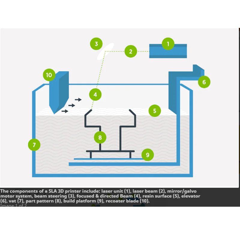
There are three main ways to operate the workspace and extruder.
X-for the following explanation-
Motion inside and outside the screen, y-
Axis motion on the screen (left-right)and z-
Up and down axis motion (
About Gravity). 1.
Keep extruder (or tool)
Fix and manipulate the work area and parts relative to the fixed head.
This means that the \"slider\" must be moved on the x, y, and z axes.
This is how most small and medium-sized CNC machines work.
This is not difficult, but the working space becomes heavy and requires a larger motor to move.
If you want to have a fast production time, a physically larger workspace will start to cause problems with quality and inertia ---
Create the problem accurately and finalize the part. 2.
Keep the working space stationary and manipulate the extruder (or tool)
About this part.
This means that the extruder moves on the x, y and z axes.
With this, you can achieve speed by keeping the moving parts small, but moving on all three axes poses some challenges and adds complexity.
The CNC machine works much faster or much larger in this way, usually because the production parts are too large, so it needs to be kept still. 3. Hybrid.
Working space and extruder (or tool)
Share 3 motion axes.
This allows you to take advantage of the benefits and reduce the drawbacks (1)and (2).
I chose this method.
I decided to press in x-
Y and work area will provide z-axis motion.
This is logical to some extent because the FDM method prints the layers at once, so most of the motion is in x-Plane anyway.
The alternative to this setup is to move the workspace in x and y while the extruder only provides z-axis motion.
The disadvantage of using a mobile workspace during FDM is that you are approaching-
The melting temperature and the Machine \"shake\" when running at high speed \".
Parallel gantry.
The parallel Gantry provides a design capability with a very light weight extruder assembly.
Since this will be a moving part, it needs to be light in weight in order to get accuracy at high speeds. Each of the x-and y-
The shaft has 3 precision shafts that introduce motion into the extruder assembly.
You can see this in the second picture.
Motor for each x-and y-
The shaft is connected to the slider through the timing belt (
Flexible belt with teeth)and pulleys.
The rotation of the motor produces the translation of the slider.
By providing sliding bushing/bearing in all positions, the action is very smooth.
The third picture shows the height of the working space in the middle. stroke.
Basically, in order to increase the height of the part, the workspace moves down slowly.
This drive is controlled by the leadscrew (
Often referred to as a ladder screw or extreme Shaft).
Throughout the design process, I need to consider the fact that I do not have the ability to produce many of these parts with the precision required to support the available components.
For example, the parallel gantry axis must be parallel to avoid bundling when moving.
To illustrate this, I avoided the support or drilling myself.
The way I explain this is by relying on a laser cutter to do all the work.
This case is not just a case, it is also the structure and features of the entire component.
Because the panel determines the shape and quality of the final part.
Each panel has interlocking tags, just like the original Makerbot design.
The design is very simple without complex curves and complex assembly steps.
I designed it in all the brackets needed to hold the device.
At the back, there is a \"shelf\" to accommodate z\"
Shaft motor and shaft used to support working space.
Because the case will be fierce.
All components of Cabinet (
Motors, bearings, etc)
Will be affected by higher temperatures
The only component I really care about is the motor.
Therefore, the motor that will do the most work (x and y axes)
Installed outside the housing to reduce heat exposure.
You will notice that there are no fasteners for the chassis panel.
I did this because I was going to glue (Solvent welding)
All components are together except the top panel.
The top panel will simply slide in place--
Allow me to remove it for maintenance/repair of other parts in the Assembly.
Other features include: the motor hole pattern is provided and the belt is allowed to be tightened.
Windows are available on all three main sides and when large parts are built, windows are closed to control the draft/temperature.
The layout of the parallel gantry looks complex but fairly symmetrical.
It is also used in McMaster or Sparkfun (motors).
The first picture shows the whole component, and the next few pictures show the details of the component.
The center of the gantry is the extruder bracket.
This is the most complex part of the component, but it is very simple at this point.
It uses the same interlocking label method as the case, but also t-
Slotted fasteners so that I can disassemble it in the future.
If I need to fix the bearings or other maintenance items in the future, I don\'t want to stick this part up.
In addition, I also include additional brackets so that multiple extruder or other tools such as dremel can be installed to provide additional performance or functionality on a later road.
However, the slider is small and just simply glued together.
The fixing shaft is fixed on a small Bolt by a large gasket.
The extruder assembly consists of two main components installed in the housing.
The motor assembly pushes the filament into the heater head.
The hub is a Makerbot project, but the tension is customized.
These parts are intended to be printed in a shape-wise way, or ask someone who owns the printer.
The filament enters from the top of the shell, and the spring fixes the idling hub on the motordriven hub.
Power the extruder using a stepping motor to better control the output
Feeding of fine silk.
This will use-
The axis port of the Makerbot electronic device.
The heater assembly is based on an idea I read online that the filament is worn through using a 5/16 ventilation screw.
The tip of the extruder is also the Makerbot project.
The actual heating element is a small piece of aluminum.
One end has a 5/16 thread to receive the discharge screw and the other end has a thread for the tip of the extruder.
Three 15 w power resistors are mounted on aluminum blocks to provide heat for melting fine wires.
The Workbench must be strong as it must hold a few pounds of plastic for larger parts.
The lower side is supported by two large-angled supports across the entire lower side.
The rear area of the Workbench is the space of the bearing.
I chose three support axes because the cantilever would be high in terms of larger parts.
Offsetting one of the axes provides a correction moment to offset the weight of the part.
Through the center is the Acme nut used to connect with the Acme screw.
The Workbench has a removable/replaceable top that can solve the problem of wear and tear over time, or modular problems in the future.
As an option, aluminum panels with 7 power resistors provide 105 watts of heat to maintain high temperatures to control the temperature of plastic components (
Avoid warping).
This is a very simple design, it is OK to use the bracket installation.
The size of the component still allows the workbench to extend all the way to the bottom of the chassis (
The heater is sandwiched between the legs of the table).
Includes a fan for circulating heat around the box.
As an extra talent, I have designed some filament guides to help the filament from reel to extruder.
The larger tour guide has two bellmen (
Or rounding/exiting)
Allows the filament to gently enter and exit the shell without touching the hard edges.
The large Guide rail also provides installation for the wire shaft.
The smaller guide wire has only one suction nozzle to help the filament enter the extruder.
The main parts can all be cut from the lexan/acrylic board on the laser cutting machine.
I think everything can be purchased and assembled for less than $1000.
Hope you like the design.
I like to do anything.
I believe that 3D printers and some other tools can give people complete manufacturing power in small rooms or garages.
For example, you need a part with a fancy shape to replace or upgrade your car.
Design it with CAD, print it, use printed plastic products as molds for sand casting, use your home furnace: melt some old soda cans and pour them into your casting
Boom, you have a solid metal part in a few hours and just need some finishing and installation.
Works of art, toys, and even cookware can be done.
I decided that it would have to be great to get the most out of the 3D printer.
The work space of the Makerbot series is growing, with 11 Replicator 2. 2\" x 6. 0\" x 6. 1\".
However, I think many of my own apps need a lot more work space.
That\'s why I designed a 3D printer with a horrible 16 \"x 13\" workspace. 1.
Do you want a 3d printer? YES (that was easy)
I was inspired to set up my own company after following etopfeplon.
Net for a while. (2.
What type of manufacturing will it use? (
For the sake of common, in-
Home DIY printer is the most likely option. 3.
How big is the working space?
Huge, 16 \"x 16\" should do 4.
How will it move?
Stepping Motor controlled by Makerbot electronics.
There are three main ways to operate the workspace and extruder.
X-for the following explanation-
Motion inside and outside the screen, y-
Axis motion on the screen (left-right)and z-
Up and down axis motion (
About Gravity). 1.
Keep extruder (or tool)
Fix and manipulate the work area and parts relative to the fixed head.
This means that the \"slider\" must be moved on the x, y, and z axes.
This is how most small and medium-sized CNC machines work.
This is not difficult, but the working space becomes heavy and requires a larger motor to move.
If you want to have a fast production time, a physically larger workspace will start to cause problems with quality and inertia ---
Create the problem accurately and finalize the part. 2.
Keep the working space stationary and manipulate the extruder (or tool)
About this part.
This means that the extruder moves on the x, y and z axes.
With this, you can achieve speed by keeping the moving parts small, but moving on all three axes poses some challenges and adds complexity.
The CNC machine works much faster or much larger in this way, usually because the production parts are too large, so it needs to be kept still. 3. Hybrid.
Working space and extruder (or tool)
Share 3 motion axes.
This allows you to take advantage of the benefits and reduce the drawbacks (1)and (2).
I chose this method.
I decided to press in x-
Y and work area will provide z-axis motion.
This is logical to some extent because the FDM method prints the layers at once, so most of the motion is in x-Plane anyway.
The alternative to this setup is to move the workspace in x and y while the extruder only provides z-axis motion.
The disadvantage of using a mobile workspace during FDM is that you are approaching-
The melting temperature and the Machine \"shake\" when running at high speed \".
Parallel gantry.
The parallel Gantry provides a design capability with a very light weight extruder assembly.
Since this will be a moving part, it needs to be light in weight in order to get accuracy at high speeds. Each of the x-and y-
The shaft has 3 precision shafts that introduce motion into the extruder assembly.
You can see this in the second picture.
Motor for each x-and y-
The shaft is connected to the slider through the timing belt (
Flexible belt with teeth)and pulleys.
The rotation of the motor produces the translation of the slider.
By providing sliding bushing/bearing in all positions, the action is very smooth.
The third picture shows the height of the working space in the middle. stroke.
Basically, in order to increase the height of the part, the workspace moves down slowly.
This drive is controlled by the leadscrew (
Often referred to as a ladder screw or extreme Shaft).
Throughout the design process, I need to consider the fact that I do not have the ability to produce many of these parts with the precision required to support the available components.
For example, the parallel gantry axis must be parallel to avoid bundling when moving.
To illustrate this, I avoided the support or drilling myself.
The way I explain this is by relying on a laser cutter to do all the work.
This case is not just a case, it is also the structure and features of the entire component.
Because the panel determines the shape and quality of the final part.
Each panel has interlocking tags, just like the original Makerbot design.
The design is very simple without complex curves and complex assembly steps.
I designed it in all the brackets needed to hold the device.
At the back, there is a \"shelf\" to accommodate z\"
Shaft motor and shaft used to support working space.
Because the case will be fierce.
All components of Cabinet (
Motors, bearings, etc)
Will be affected by higher temperatures
The only component I really care about is the motor.
Therefore, the motor that will do the most work (x and y axes)
Installed outside the housing to reduce heat exposure.
You will notice that there are no fasteners for the chassis panel.
I did this because I was going to glue (Solvent welding)
All components are together except the top panel.
The top panel will simply slide in place--
Allow me to remove it for maintenance/repair of other parts in the Assembly.
Other features include: the motor hole pattern is provided and the belt is allowed to be tightened.
Windows are available on all three main sides and when large parts are built, windows are closed to control the draft/temperature.
The layout of the parallel gantry looks complex but fairly symmetrical.
It is also used in McMaster or Sparkfun (motors).
The first picture shows the whole component, and the next few pictures show the details of the component.
The center of the gantry is the extruder bracket.
This is the most complex part of the component, but it is very simple at this point.
It uses the same interlocking label method as the case, but also t-
Slotted fasteners so that I can disassemble it in the future.
If I need to fix the bearings or other maintenance items in the future, I don\'t want to stick this part up.
In addition, I also include additional brackets so that multiple extruder or other tools such as dremel can be installed to provide additional performance or functionality on a later road.
However, the slider is small and just simply glued together.
The fixing shaft is fixed on a small Bolt by a large gasket.
The extruder assembly consists of two main components installed in the housing.
The motor assembly pushes the filament into the heater head.
The hub is a Makerbot project, but the tension is customized.
These parts are intended to be printed in a shape-wise way, or ask someone who owns the printer.
The filament enters from the top of the shell, and the spring fixes the idling hub on the motordriven hub.
Power the extruder using a stepping motor to better control the output
Feeding of fine silk.
This will use-
The axis port of the Makerbot electronic device.
The heater assembly is based on an idea I read online that the filament is worn through using a 5/16 ventilation screw.
The tip of the extruder is also the Makerbot project.
The actual heating element is a small piece of aluminum.
One end has a 5/16 thread to receive the discharge screw and the other end has a thread for the tip of the extruder.
Three 15 w power resistors are mounted on aluminum blocks to provide heat for melting fine wires.
The Workbench must be strong as it must hold a few pounds of plastic for larger parts.
The lower side is supported by two large-angled supports across the entire lower side.
The rear area of the Workbench is the space of the bearing.
I chose three support axes because the cantilever would be high in terms of larger parts.
Offsetting one of the axes provides a correction moment to offset the weight of the part.
Through the center is the Acme nut used to connect with the Acme screw.
The Workbench has a removable/replaceable top that can solve the problem of wear and tear over time, or modular problems in the future.
As an option, aluminum panels with 7 power resistors provide 105 watts of heat to maintain high temperatures to control the temperature of plastic components (
Avoid warping).
This is a very simple design, it is OK to use the bracket installation.
The size of the component still allows the workbench to extend all the way to the bottom of the chassis (
The heater is sandwiched between the legs of the table).
Includes a fan for circulating heat around the box.
As an extra talent, I have designed some filament guides to help the filament from reel to extruder.
The larger tour guide has two bellmen (
Or rounding/exiting)
Allows the filament to gently enter and exit the shell without touching the hard edges.
The large Guide rail also provides installation for the wire shaft.
The smaller guide wire has only one suction nozzle to help the filament enter the extruder.
The main parts can all be cut from the lexan/acrylic board on the laser cutting machine.
I think everything can be purchased and assembled for less than $1000.
Hope you like the design.
Custom message
Related Products