towell@sztuowei.com


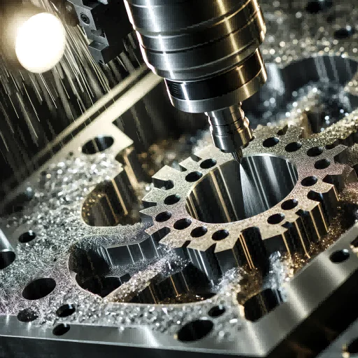
How to Reduce CNC Machining Costs
fsla 3d printer
by:Tuowei
2019-09-01
This guide covers the construction and installation of the \"low cost\" 3d printer SLA.
The project started during Christmas 2014, when I was busy with another project that completely attracted me.
During the holidays, I decided (unconsciously)
Distract yourself with the idea of creating a printer based on photosensitive resin technology.
The idea is to control the UV laser module installed on the central joint and tilt it to all the points planned.
After it was done and put into operation, I realized that there were several issues with it.
One of the biggest problems is related to the accuracy of motion (
Although the economic step driver has been divided into many steps, the single step is unreliable for such operations)
, Another big problem is the deformation of the beam when it reaches the bottom, and depending on where it is, it takes a different form.
After some less satisfactory testing and printing, I decided to switch to the traditional Descartes structure instead.
Finally, naively thought it took me three months to complete the whole work before January, but I was happy with the results!
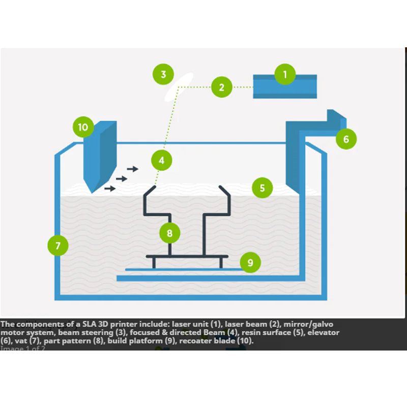
At this point, it is better to step back and talk about SLA printing technology.
This type of printing is based on the principle that it is possible to hit a small amount of resin with a coherent photon beam.
The resin provided on the market for this purpose is sensitive to UV 40nm.
Satisfaction with the makerjuice museum I used before.
From a practical point of view, this means that the uv laser is used for layer-by-layer catalysis, where each layer represents a part of the object we want to achieve.
Layer of required thickness for catalysis (ex. 0. 1mm)
There are two basic technologies.
One technique is the layers on the catalytic plate that gradually descend into a tank filled with resin, each of which is catalytic on the previous layer.
The floor always drops the same size relative to the resin surface, which corresponds to the thickness of the layer.
The second method (
The one I chose)provides a UV-
Transparent Container, containing resin, under the laser of the catalytic resin.
To build the model, the printer moves the plane inside the container to maintain the required thickness between the plane itself and the bottom of the tank.
Between the first and next layers, the aircraft is lifted, and in order to leave free space for the next layer, the aircraft must remain attached to it.
Both methods work, but there are different problems.
The first method requires a storage tank with a volume equal to the maximum building volume and is filled at least to the height of the workpiece (
This is a problem for people who don\'t use the resin that will last for a long time, or you have to remove it often).
It also requires a reliable system to control the level of the resin and the sinking of the floor, as going through the volume change of the catalytic resin will affect the results.
The second method is simpler, but there are some problems.
The most annoying thing is that when catalytic to the bottom of the plate and container, the resin sticks, and then, when planning to lift to the next layer, it is necessary to ensure that the material remains attached to the plate, instead of attaching to the tank, the print fails otherwise.
To avoid this, we need to create a fund in the container but transparent to UV because the laser has to pass through it.
It is also important to avoid the \"suction cup effect\", which occurs when trying to separate two surfaces that adhere and apply forces perpendicular to the plane.
To do this, the movement of the inclined bathtub is expected in the printer, removing the resin from the plane from the edge.
4x: 20mm rod support (0612-SHF20)
2 x: 20mm bearing bracket for z axis (0548-TBR20UU)
For screws with Z-axis 2x: 20mm bars (ST20)4x: foot (TCOL00157398)4 x: 30x240 C
Introduction to monthly allumium (PR0300308)
Bottom and top (
The top and bottom should be M8 thread)4 x: 30x300 C
Introduction to monthly allumium (PR0300308)
Bottom and top (
The top and bottom should be M8 thread)
4 X: 30x30R round allumium profile (PR030030R)for the jambs (
The top and bottom should be M8 thread)
1x: 45x90x200 allumium profile (PR0300908)
Flat plate holder 2x: 60x30x290 allumium plate for z axis (
See dxf for more details)
2x: D12 slide frame for z axis (0548-TBR20UU)
1x: 350x290x3 allumium plate for boat board support (
See dxf for more details)
Clamping: Clamping Angle 25x40 (SQ025040)
Install the Z axis to the structural 16x: M8 Bolt C
3d printer compatible electronic products (Arduino based)
1x: reprap compatible LCD 3x: step motor NEMA17 0.
9 °/step for x y z axis1x: step motor NEMA17/gearboxe 0.
35 °/step of Vessel1x: Z axisa for carriers, brackets, etc a bunch of screw nuts for 3d printed parts. . (
View files that come with stl)
This material should be found in the store where 3d printers or cnc mechanical parts are sold.
I found all the Cnc stuff.
Good price and service.
I called the printer FSLA because it was Fla (my name)andSLA (
Stereo printing).
The building volume of the printer is 150x130mm, which is larger than the usual volume in the sla low cost printer. .
The structure is based on the extruded aluminum section of the 30mm side, which is mounted with a slide frame for laser motion, a bathtub support and a bar for the z axis.
The main frame is built around 4 jambs, these jambs are 30x30 round sections and I think it looks pretty :)
To install 4 square sections of 30x30 for the edge, you should make 4 holes in the round section.
These holes must be 15mm away from the top and bottom, and should pass through the middle of the central cavity of the part where the bolt head must be.
Each edge is fixed on jamb by M8 round bolt, and the hole is where the Allen key is used to tighten the bolt.
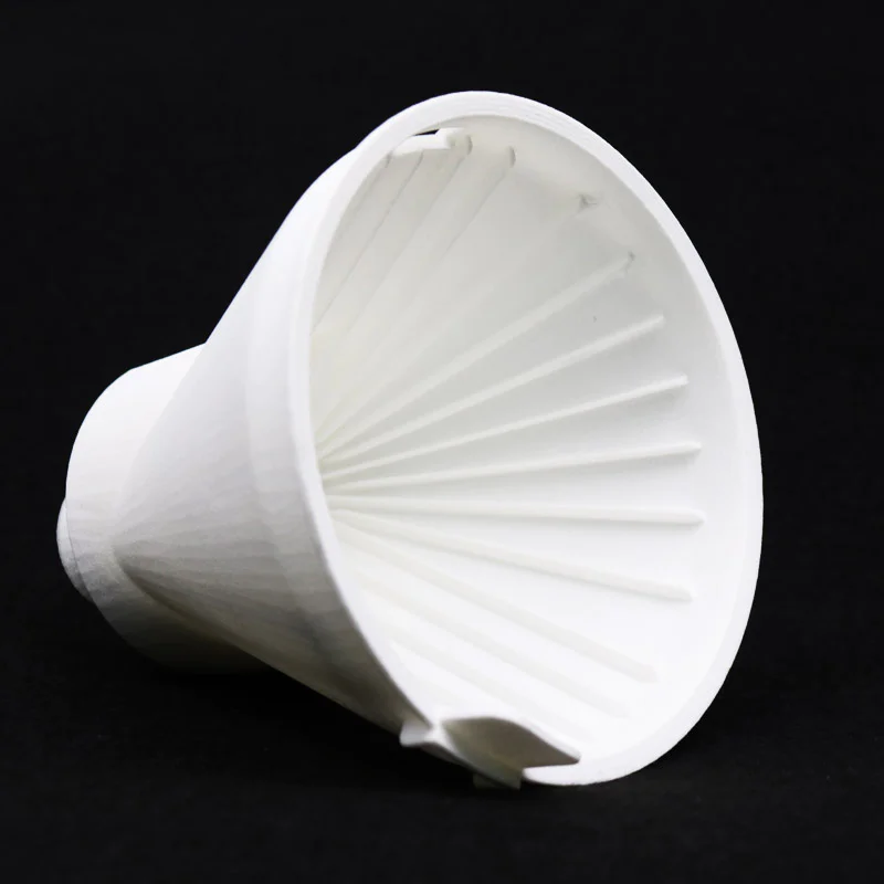
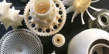
All the components needed to build the axis X and Y can be printed out from a normal FDM printer, and I personally prefer PLA as a material, but I think abs and nylon are also perfect.
In this guide, you can find all stl files for printing.
In order to make the carriage slide perfectly, I used the sliding bearing, while in terms of the towing belt, I used the 5mm spacing 10mm wide.
For X, Y, and Z, I used the NEMA17 Model 42 byghm809 (0. 9 ° / step)
When I use the 42 sth38 motor, the tilt of the tub is always the NEMA17 with the gearbox (0:35 ° / step).
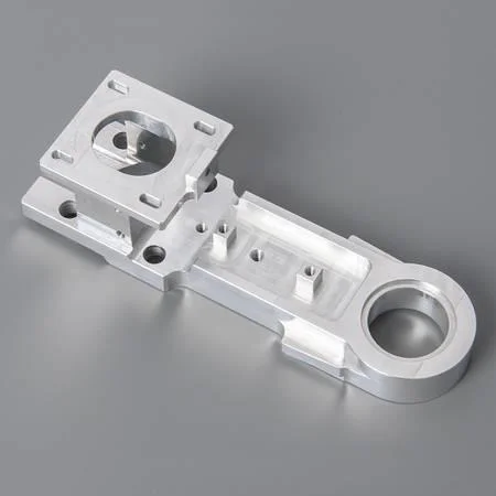
To ensure the good strength of the machine, I made some aluminum parts, especially the support of the z axis and the container.
To implement these parts, I have attached the file dxf and gcode for cnc milling cutting.
Regarding the z axis, I decided to use the screw with the ball nut instead of moving with the belt.
This type of mechanism is expensive, but allows you to move the plane on the vertical axis, greatly reducing friction and gaming.
The two vertical bars are big, but if you want a solid Z-axis.
Regarding the structure of the water tank, I cut some glass from the glass and assembled it with silicone acetate.
What we must pay special attention to isstick coating.
This is critical to the success of the print! !
In fact, the resin has to adhere better to the plane than to the bathtub in order to keep the attached part of the print.
I used two for this-
The components are liquid silicone and UV transparent for the protection of photovoltaic panels.
The only thing I \'ve tried and found to be good about this is Sylgard 184 and QSIL 216, which I ended up using at a lower price and availability.
When depositing silicone, in order to ensure that the tank is horizontal, so that the thickness of the layer is uniform, it is also advisable to remove the bubbles that will keep the package, either manually or by ringing the bell.
To make sure the tank is fixed on the bracket, I used two aluminum rails in which the container boundary flows.
The laser I use is a module of 120 mA 40nm, which is controlled by the power supply, which allows digital control input up to 20 KHz in addition to adjusting the current.
This allows me to change the laser power using the pins of uC.
To prevent UV radiation in the environment from really hardening the resin, I have realized that some acrylic panels, some clear orange and other black, where the interior parts will be hidden.
Regarding electronic products, I used the circuit board produced at www. futurashop.
It companies that drag printers for their 3 to achieve this.
I chose it because I thought it did a good job, but there was a slight change in the firmware and you could use any other electronics designed with an Arduino-based 3d printer.
The firmware I started was well known for Marin and made the appropriate changes to get my laser printer running.
For example, it is usually used to push the E-axis of the material, in my case, to tilt the container between one layer and the other.
Pwm control for uv laser (
Laser power can be changed by changing the duty cycle)
I use the pins of the uC, which are usually used to control the power mosfet on the heated surface.
You can check the firmware of the FSLA printer on my github printer, or you can be considered \"versatile\" as I have used it satisfactorily to implement the pcb.
In fact, the laser used for catalytic resin can also be used to impress the anti-etching on the pre-sensitive plate for light etching.
To do this, I usually design pcb using Eagle PCB and then make gcode using modified version of eaglePCB, PCB-well known ulpGcode.
In order to impress the pre-sensitive plate, you have to remove the container and install the plate to the plate with two screws.
If the board is a double sided pcb, you must print the top first, then rotate the board on the board and print the bottom.
In order to align the two photos, you must accurately measure the offset on the x-axis when you mirror the board and spin (
Because you may not be accurate enough for the holes and the structure itself).
This is not an easy process, but when you are done you have to modify my settings in \"/scr/pcb2FSLAprinter.
Before launching the script inside the eagle pcb, first put the \"scr\" file.
After the printing is done, you can process the circuit board as you do during normal light flushing so you can use sodium hydroxide and then remove the copper with hydrogen peroxide.
I think this printer is more useful for people who like to print parts with higher resolution but without mechanical use.
This is because the print is made of resin, even if there are several uv resins, the print is more used for action drawings or design objects, not much for those who want to set up the mechanism.
This is my experience so far, but every day there is news about UV resin and maybe there is better news already.
The construction of this machine was a very good adventure and I thought it was harder but in the end I thought resault was really good! !
The cost of this project cannot be ignored, and it is not easy to build, but when to start working (
It will work :))
Will be very satisfied with you.
I know there\'s a lot to say in order to have the complete information to build the machine, but I hope the images can help anyone who wants to try to build the machine.
I will certainly be here if anyone needs more information.
I really hope you enjoyed the instructions.
Maybe someone will make this machine and may improve the project! !
The project started during Christmas 2014, when I was busy with another project that completely attracted me.
During the holidays, I decided (unconsciously)
Distract yourself with the idea of creating a printer based on photosensitive resin technology.
The idea is to control the UV laser module installed on the central joint and tilt it to all the points planned.
After it was done and put into operation, I realized that there were several issues with it.
One of the biggest problems is related to the accuracy of motion (
Although the economic step driver has been divided into many steps, the single step is unreliable for such operations)
, Another big problem is the deformation of the beam when it reaches the bottom, and depending on where it is, it takes a different form.
After some less satisfactory testing and printing, I decided to switch to the traditional Descartes structure instead.
Finally, naively thought it took me three months to complete the whole work before January, but I was happy with the results!
At this point, it is better to step back and talk about SLA printing technology.
This type of printing is based on the principle that it is possible to hit a small amount of resin with a coherent photon beam.
The resin provided on the market for this purpose is sensitive to UV 40nm.
Satisfaction with the makerjuice museum I used before.
From a practical point of view, this means that the uv laser is used for layer-by-layer catalysis, where each layer represents a part of the object we want to achieve.
Layer of required thickness for catalysis (ex. 0. 1mm)
There are two basic technologies.
One technique is the layers on the catalytic plate that gradually descend into a tank filled with resin, each of which is catalytic on the previous layer.
The floor always drops the same size relative to the resin surface, which corresponds to the thickness of the layer.
The second method (
The one I chose)provides a UV-
Transparent Container, containing resin, under the laser of the catalytic resin.
To build the model, the printer moves the plane inside the container to maintain the required thickness between the plane itself and the bottom of the tank.
Between the first and next layers, the aircraft is lifted, and in order to leave free space for the next layer, the aircraft must remain attached to it.
Both methods work, but there are different problems.
The first method requires a storage tank with a volume equal to the maximum building volume and is filled at least to the height of the workpiece (
This is a problem for people who don\'t use the resin that will last for a long time, or you have to remove it often).
It also requires a reliable system to control the level of the resin and the sinking of the floor, as going through the volume change of the catalytic resin will affect the results.
The second method is simpler, but there are some problems.
The most annoying thing is that when catalytic to the bottom of the plate and container, the resin sticks, and then, when planning to lift to the next layer, it is necessary to ensure that the material remains attached to the plate, instead of attaching to the tank, the print fails otherwise.
To avoid this, we need to create a fund in the container but transparent to UV because the laser has to pass through it.
It is also important to avoid the \"suction cup effect\", which occurs when trying to separate two surfaces that adhere and apply forces perpendicular to the plane.
To do this, the movement of the inclined bathtub is expected in the printer, removing the resin from the plane from the edge.
4x: 20mm rod support (0612-SHF20)
2 x: 20mm bearing bracket for z axis (0548-TBR20UU)
For screws with Z-axis 2x: 20mm bars (ST20)4x: foot (TCOL00157398)4 x: 30x240 C
Introduction to monthly allumium (PR0300308)
Bottom and top (
The top and bottom should be M8 thread)4 x: 30x300 C
Introduction to monthly allumium (PR0300308)
Bottom and top (
The top and bottom should be M8 thread)
4 X: 30x30R round allumium profile (PR030030R)for the jambs (
The top and bottom should be M8 thread)
1x: 45x90x200 allumium profile (PR0300908)
Flat plate holder 2x: 60x30x290 allumium plate for z axis (
See dxf for more details)
2x: D12 slide frame for z axis (0548-TBR20UU)
1x: 350x290x3 allumium plate for boat board support (
See dxf for more details)
Clamping: Clamping Angle 25x40 (SQ025040)
Install the Z axis to the structural 16x: M8 Bolt C
3d printer compatible electronic products (Arduino based)
1x: reprap compatible LCD 3x: step motor NEMA17 0.
9 °/step for x y z axis1x: step motor NEMA17/gearboxe 0.
35 °/step of Vessel1x: Z axisa for carriers, brackets, etc a bunch of screw nuts for 3d printed parts. . (
View files that come with stl)
This material should be found in the store where 3d printers or cnc mechanical parts are sold.
I found all the Cnc stuff.
Good price and service.
I called the printer FSLA because it was Fla (my name)andSLA (
Stereo printing).
The building volume of the printer is 150x130mm, which is larger than the usual volume in the sla low cost printer. .
The structure is based on the extruded aluminum section of the 30mm side, which is mounted with a slide frame for laser motion, a bathtub support and a bar for the z axis.
The main frame is built around 4 jambs, these jambs are 30x30 round sections and I think it looks pretty :)
To install 4 square sections of 30x30 for the edge, you should make 4 holes in the round section.
These holes must be 15mm away from the top and bottom, and should pass through the middle of the central cavity of the part where the bolt head must be.
Each edge is fixed on jamb by M8 round bolt, and the hole is where the Allen key is used to tighten the bolt.
All the components needed to build the axis X and Y can be printed out from a normal FDM printer, and I personally prefer PLA as a material, but I think abs and nylon are also perfect.
In this guide, you can find all stl files for printing.
In order to make the carriage slide perfectly, I used the sliding bearing, while in terms of the towing belt, I used the 5mm spacing 10mm wide.
For X, Y, and Z, I used the NEMA17 Model 42 byghm809 (0. 9 ° / step)
When I use the 42 sth38 motor, the tilt of the tub is always the NEMA17 with the gearbox (0:35 ° / step).
To ensure the good strength of the machine, I made some aluminum parts, especially the support of the z axis and the container.
To implement these parts, I have attached the file dxf and gcode for cnc milling cutting.
Regarding the z axis, I decided to use the screw with the ball nut instead of moving with the belt.
This type of mechanism is expensive, but allows you to move the plane on the vertical axis, greatly reducing friction and gaming.
The two vertical bars are big, but if you want a solid Z-axis.
Regarding the structure of the water tank, I cut some glass from the glass and assembled it with silicone acetate.
What we must pay special attention to isstick coating.
This is critical to the success of the print! !
In fact, the resin has to adhere better to the plane than to the bathtub in order to keep the attached part of the print.
I used two for this-
The components are liquid silicone and UV transparent for the protection of photovoltaic panels.
The only thing I \'ve tried and found to be good about this is Sylgard 184 and QSIL 216, which I ended up using at a lower price and availability.
When depositing silicone, in order to ensure that the tank is horizontal, so that the thickness of the layer is uniform, it is also advisable to remove the bubbles that will keep the package, either manually or by ringing the bell.
To make sure the tank is fixed on the bracket, I used two aluminum rails in which the container boundary flows.
The laser I use is a module of 120 mA 40nm, which is controlled by the power supply, which allows digital control input up to 20 KHz in addition to adjusting the current.
This allows me to change the laser power using the pins of uC.
To prevent UV radiation in the environment from really hardening the resin, I have realized that some acrylic panels, some clear orange and other black, where the interior parts will be hidden.
Regarding electronic products, I used the circuit board produced at www. futurashop.
It companies that drag printers for their 3 to achieve this.
I chose it because I thought it did a good job, but there was a slight change in the firmware and you could use any other electronics designed with an Arduino-based 3d printer.
The firmware I started was well known for Marin and made the appropriate changes to get my laser printer running.
For example, it is usually used to push the E-axis of the material, in my case, to tilt the container between one layer and the other.
Pwm control for uv laser (
Laser power can be changed by changing the duty cycle)
I use the pins of the uC, which are usually used to control the power mosfet on the heated surface.
You can check the firmware of the FSLA printer on my github printer, or you can be considered \"versatile\" as I have used it satisfactorily to implement the pcb.
In fact, the laser used for catalytic resin can also be used to impress the anti-etching on the pre-sensitive plate for light etching.
To do this, I usually design pcb using Eagle PCB and then make gcode using modified version of eaglePCB, PCB-well known ulpGcode.
In order to impress the pre-sensitive plate, you have to remove the container and install the plate to the plate with two screws.
If the board is a double sided pcb, you must print the top first, then rotate the board on the board and print the bottom.
In order to align the two photos, you must accurately measure the offset on the x-axis when you mirror the board and spin (
Because you may not be accurate enough for the holes and the structure itself).
This is not an easy process, but when you are done you have to modify my settings in \"/scr/pcb2FSLAprinter.
Before launching the script inside the eagle pcb, first put the \"scr\" file.
After the printing is done, you can process the circuit board as you do during normal light flushing so you can use sodium hydroxide and then remove the copper with hydrogen peroxide.
I think this printer is more useful for people who like to print parts with higher resolution but without mechanical use.
This is because the print is made of resin, even if there are several uv resins, the print is more used for action drawings or design objects, not much for those who want to set up the mechanism.
This is my experience so far, but every day there is news about UV resin and maybe there is better news already.
The construction of this machine was a very good adventure and I thought it was harder but in the end I thought resault was really good! !
The cost of this project cannot be ignored, and it is not easy to build, but when to start working (
It will work :))
Will be very satisfied with you.
I know there\'s a lot to say in order to have the complete information to build the machine, but I hope the images can help anyone who wants to try to build the machine.
I will certainly be here if anyone needs more information.
I really hope you enjoyed the instructions.
Maybe someone will make this machine and may improve the project! !
Custom message
Related Products